The GL2000 is a 4 channel standalone data logger suitable for high voltage and true RMS monitoring. The logger has 4 channels capable of logging AC voltages up to 1000V (CAT III up to 600vAC). Analogue inputs are also suitable for use with K, J, E, T, R, S, B, N and W Type Thermocouples. The GL2000 comes with a wide 7" wide TFT colour LCD with waveform or digital options. 4 individual A/D converters allow all 4 channels to be logged at 1µs to the internal memory and at 100kHz to an external memory, USB or SD memory card. The Trigger function allows the unit to wait for a specific input value to start and stop logging, limiting high speed logging to capture specific data for fault diagnosis.
High speed 1 MS/s simultaneous sampling with isolated input
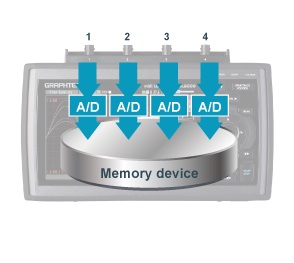
GL2000 is equipped with an isolated input mechanism to protect signals from interference caused by noise from other channels. 16-bit A/D converter adopted to achieve hi-speed and hi-resolution measurement.
 Simultaneous sampling
GL2000 utilizes simultaneous sampling to eliminate slowdown in sampling rate by using multiple A/D converters in simultaneous sampling method. Four individual A/D converters in each channel sustains the maximum sampling speed for all four channels to measure high speed rapid voltage fluctuation and multi-channel vibration measurement.
Sampling interval: 1 µs to 1 min (in steps of 1, 2, 5)
External sampling function
Sampling of the logger is performed in sync with an external device using an external signal input.
Maximum input frequency: 100 kHz
* B-513 Input/Output cable for GL is required.
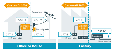
Multi-function input with CAT III measurement category
Voltage, temperature, humidity, logic and pulse measurements can all be taken simultaneously in high speed.
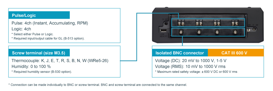
CAT III 600 V is compatible with measuring power supply circuit in an equipment that captures power directly from the distribution panel.
Measures abnormalities in a repeated waveform by effectively measuring the corresponding RMS value
- In 1000 Vrms range, Crest Factor is up to 1.41
* Maximum rated safety voltage: 600 V rms, Peak voltage: 850V - In other range, Crest Factor is up to 2.0

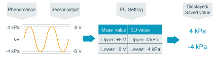
Scaling (Engineering unit) function
Measured voltage value can be converted to a specified engineering unit. The value can be displayed with the physical measurement value of the sensor and be saved into the data file with the converted values.
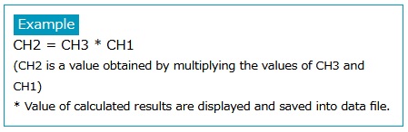
Calculation function between channels
Four arithmetic operations (Addition, subtraction, multiplication and division) are available using two analog input channels.
* Data can be saved only in GBD file format.
Trigger function
The trigger in this unit has multiple functions including level trigger of input signal value for each channel.
Trigger action Start or stop capturing data by triggering Trigger source Off, Measured signal level, Alarm, External, Scheduled time, Scheduled day, Elapsed time
* When trigger is used for starting action, level of measured signal can be set for each channel. Threshold
Analog input:
High or Rising, Low or Falling, Window-in, Window-out
Logic input:
H or L (4-channel signal pattern)
Pulse input:
High or Rising, Low or Falling, Window-in, Window-out
Combination:
Level OR, Level AND, Edge OR, Edge AND
Alarm function & signal output
Threshold of an alarm can be set for each channel. When an alarm occurs, notification is sent by following methods.
Alarm threshold
Analog input:
High, Low, Window-in, Window-out
Logic input:
H or L (signal in each channel)
Pulse input:
High or Rising, Low or Falling, Window-in, Window-out
When alarm is detected
- Display to screen (Digital value of alarm's origin channel is displayed in red)
- Save alarm information to measurement data file
- Output alarm signal
Number of channel:
4 channels (Output channel can be arranged to each source channel in OR condition.)
Signal type:
Open collector (pull-up to 5 V with 10 kΩ resistor), maximum load is the 24 V and 100 mA.
* Requires Input/Output cable for GL series (B-513 Option).
Large Easy-to-read 7-inch LCD
Monitor data in multiple methods in addition to digital value display and full waveform display screen.
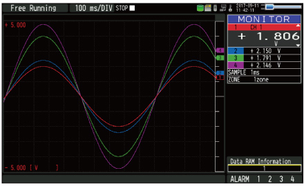
Y-T waveform monitor screenDisplays data with analog waveform and digital value. Screen can also be split into 1, 2, 4 or 8 zones to display the channels in different zones.
|
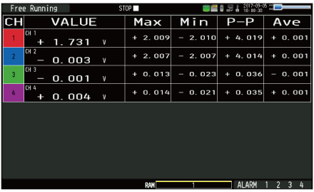
Digital monitor screenDisplays current data in digital value and results of real time statistical calculation. (Function: Maximum, Minimum, Peak-to-peak, and Average) |
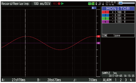
Past waveform monitor screenDisplay the past part of the data while capturing data. Execute without stopping measurement and also scroll past data. Data screen can be switched with past and current. |
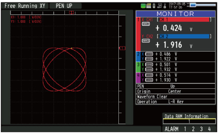
XY graph monitor screenEmulates the classic XY chart recorder. Also supports features for pen up/down and position movement.
|
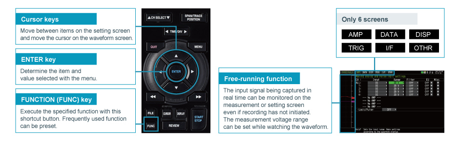
Quick and Easy Set Up Process
Simple operation with cursor and enter keys, and menu-driven operation with six pre-set menu screens: AMP, DATA, DISP, TRIG, I/F (Interface) and OTHER.
Other helpful functions
Delivers reliable measurements out at a location with unstable power supply.
Equipped with three types of options for power source, AC adapter, DC input, and battery pack. With a battery pack, GL2000 runs continuously for approximately 3 hours. If an AC power failure occurs, it will automatically switch from the AC adapter to the battery pack. Additionally, when the battery pack is drained, measurements will automatically stop after saving the data file preserving the accumulated data. (Requires two battery packs (B-569 option) installed.)
Instrument is in compliance with JIS Vibration Test Method for Automobile Type 1 Class A. (Vibration durability test: 5 m/s²)
Supports large built-in RAM (4MS/ch) and built-in Flash (4 GB)
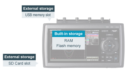 Long term recording is made possible with 4 M samples/ch built-in RAM and 4 GB built-in Flash memory. It supports both USB Flash memory and SD Card memory to be used as external storage devices for recorded data for certain sampling intervals.
Approximate recording time
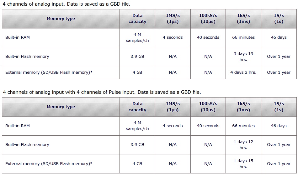
* When using 8GB or larger memory, the size of data file will be up to 4GB. The Relay mode enables extended recording time.
Convenient Data Recording Functions
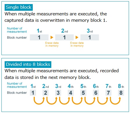
Memory division function
|
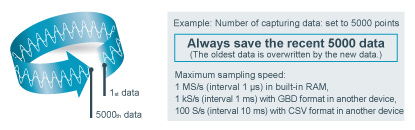
Ring mode
Saves most recent data of specified number after recording stops.Number of capturing data 1000 to 10000000 data
|
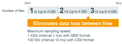
Relay mode
|
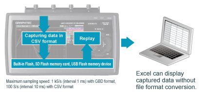
Save & replay data in CSV format
Captured data can be saved with GBD (binary) and CSV (text) format. CSV format file can be played on GL2000 and opened with spreadsheet software.
|
Data backup and hot swaps
|
Auto save function
|
Search function

The search function can locate a specific value within the captured data as well as finding abnormal values within data of a long-recorded file.
Search content
Search for analog signal levels, logic signal pattern, pulse signal levels or alarm point in captured data.
Analog signal channel:
Signal levels in each channel
・Search mode: raising, falling, window-in, window-out
Logic signal channel:
Signal level (H or L) in each channel
Pulse signal channel:
Signal levels in each channel
・Search mode: raising, falling, window-in, window-out
Alarm:
Alarm detected point on selected alarm signal output channel
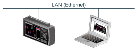
Equipped with Ethernet (LAN) and USB interface to communicate with PC
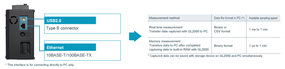
Convenient function with LAN (Ethernet interface) capability
When GL2000 is connected to LAN using the Ethernet interface, networked computer can monitor real-time measured value, transfer files, and change set ups without using application software (GL980_2000-APS software).
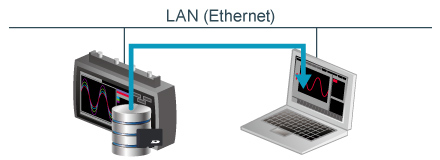
Web server functionGL2000 can be controlled externally via a network on the WEB browser, which also supports real-time monitoring and ability to use the menu buttons. |
FTP server functionFile in available storage device on GL2000 except built-in RAM can be transferred or deleted from the PC. |
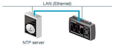
NTP client functionThe clock on the GL2000 periodically synchronises with the NTP server. |
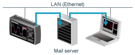
Email sending functionSend information when alarm occurs, or when battery is low, or when communication speed drops, or to notify when the space becomes limited on the storage device by an e-mail to specified address. Information may also be sent periodically by settings. |
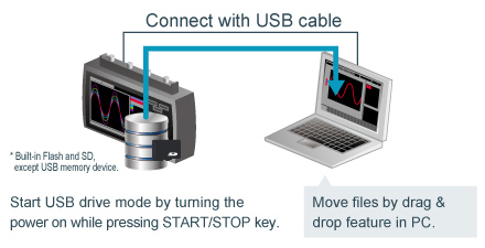
USB Drive Mode to Easily Transfer Files to PC
The USB drive mode function allows simple data transfer to the PC from built-in Flash memory and SD Flash memory card which acts as USB Flash drive on GL2000. It also allows for adding, removing, and deleting files from storage device on the GL2000 from PC file browsing explorer.