Omni Instruments
contact icon+44 (0) 1382 443000
+44 (0) 845 9000 601
WE ARE HERE TO HELP

Contact our technical sales team now to discuss your requirements

help icon
MY BASKET basket arrow

£0.00

My Cart

You have no items in your shopping cart.

Click basket to edit.

Products

Latest added news blog
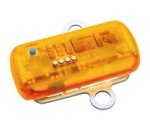
MSR175 Shock Transportation Data Logger
Kenny Laidlaw
Oct 01,2018
The MSR175 shock transportation data logger is the newest miniature logger from MSR.  The MSR175 ut...read more >
MS-IMU3050 MEMS Inertial Measurement Unit
  • MS-IMU3050 MEMS Inertial Measurement Unit

MS-IMU3050 MEMS Inertial Measurement Unit

Quick Overview

The MS-IMU3050 is a high performance MEMS Inertial Measurement Unit (IMU). The MS-IMU3050 contains triaxial MEMS gyros, accelerometers and magnetometers that are extensively tested and calibrated over the full operational temperature range to ensure the highest performance and robust operation. Gyro Bias Stability of 0.40 °/h, Accelerometer Bias Stability of 40 µg. The MS-IMU3050 IMU provides all this in a package that measures 40.6 x 45.7 x 25mm with a mass of only 60 grams.

Details

Applications

  • Navigation Systems
  • Pipeline Inspection
  • Platform Stabilization
  • UAS Navigation and Control
  • Surveying
  • Robotics
  • Orientation Control

Features

  • Gyro Bias Stability of 0.33 °/h
  • Accelerometer Bias Stability of 21 µg
  • Low Noise Accelerometers 27 µg/√Hz Noise Density
  • User configurable
  • Miniature Package 45.7 x 40.6 x 25mm
  • Light Weight at 60 grams


The coordinate system for the MS-IMU3050 follows the right hand rule convention. As an example, with the inertial measurement unit pictured in Figure 2, if the Z axis is pointed straight UP away from the earth, it will produce 0 g for the X and Y axes and a positive 1 g for the Z axis. A counterclockwise rotation of the IMU about any of the depicted axis will produce a positive angular rate output for the corresponding axis. The magnetometer sign convention produces a positive output on the corresponding axis aligned in the North direction with the IMU bottom parallel and facing the Earth’s surface.

Specifications

Power Supply: 4.9vDC @ 600mA
Operating Temp: -40 to +85°C
Dimensions:
 45.7 x 40.6 x 25mm (L x W x H)
Connector: 9-pin MIL-DTL-32139
Output: RS422


Sensors

  Gyroscope Accelerometer Magnetometer
Dynamic Range ±480°/s. ±10g ±2.0 gauss
Bias Instability 0.33°/h max 21µg  
Offset  ±10°/h ±2.4mg ±0.03 gauss
Non-linearity 0.05%FS  ±0.3%FS 0.5%FS
Random Walk 0.08 °/√h 0.02 m/s/√h  
Noise Density 0.002 °/s/√Hz 27 μg/√Hz 350 μgauss/√Hz
Internal Sampling Rate 800Hz
Bandwidth (-3dB) Default 50Hz


The gyro bias stability of 0.33 degree per hour and accelerometer bias stability of 21 micro g supply ample inertial performance to support a range of applications from Unmanned Aircraft System (UAS) navigation or positioning and stablisation applications. User configurable options allow the IMU to be tuned to your application.

The MS-IMU3050 is contained in an ultra-durable MIC-6 alloy housing with a MIL-A-8625 coating and military standard interface connector. Mounting of the IMU is achieved through four captive socket head cap screws. The mounting surface of the mechanical interface is flat to within one one-thousandths of an inch. The dimensions above are only an overview of the housing, detailed mechanical drawings in Imperial and Metric units are available on request.

MS-IMU3050 Dimensional Drawing


Availability: Stock Item