

Description
The DBBSMM series miniature ‘S-beam load cell’ is designed for force measurement and weighing applications alike and can be used for tension and compression measurements. It’s ease of mounting makes it very attractive for use as a general purpose load cell. The DBBSMM is a miniature version of the DBBSM Series load cells and ideal for applications where space is limited and capacity is low.
Features
- Capacities 1 to 50Kg
- Only 35mm High
- Robust Construction
- Simple Installation
- High Accuracy : <±0.03%/RC
- High Side Load Resistance
- 3-YEAR Manufacturer Warranty
- Sealed to IP51, IP67 Version available for more ardous applications
Options
- Other Ranges Available on Request
- Spherical Rod End Bearings
- Load Buttons
- Different Cable Lengths
- Full Range of Mounting Options Available (consult factory)
- 500VAC Certification
Applications
- Force & Load Measurement Applications
- Suspended Hoppers
- Geotechnical Test Equipment
- Tensile Testing Machines
- Wave Tank Monitoring (IP67 version)
Specifications
| Standard Capacities (Kgf): | 0-1, 0-2, 0-5, 0-10, 0-25, 0-50 |
| Sensitivity: | 2mv/V Nominal |
| Zero Balance/Offset: | <±1.0% Rated Output |
| Non-Linearity: | <±0.03% Rated Output |
| Hysteresis: | <±0.03% Rated Output |
| Repeatability: | <±0.02% Rated Output |
| Input Resistance: | 375 Ohms Nominal |
| Output Resistance: | 350 Ohms Nominal |
| Insulation Resistance: | >5000 @ 50vDC |
| Excitation Voltage: | 10vDC Recommended (2-15vDC Acceptable) |
| Operating Temperature: | -20 to +80°C |
| Compensated Temperature: | 0 to +70°C |
| Storage Temperature: | -20 to +80°C |
| Safe Overload: | 150% of Rated Capacity |
| Ultimate Overload: | 200% of Rated Capacity |
| Maximum Safe Side Load: | 30% of Rated Capacity |
| IP Rating: | Standard IP51, IP67 available on request |
| Fatigue Life: | 108 Cycles Typical (109 cycles on fatigue-rated version) |
| Cable: | 2m, 4-Core Screened, PVC Sheath ¶Ø3.5 nominal |
| Construction: | Aluminium Alloy |
Dimensions
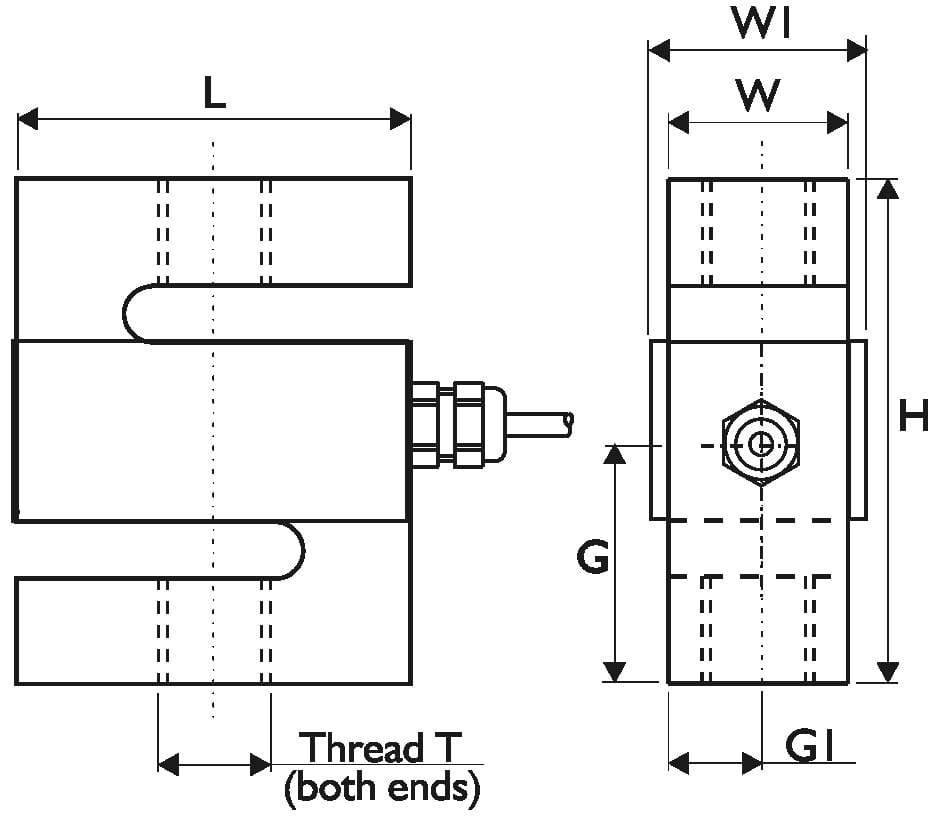
Note: Load cells with capacities over 10,000Kg will have rounded shoulders.
| Capacity | H | L | ¶W | W1 | G | G1 | Threads T | Weight |
| 0-1Kgf | 35 | 24 | 12 | 16 | 17.5 | 6 | M6 x 1.0 | 25g |
| 0-2Kgf | 35 | 24 | 12 | 16 | 17.5 | 6 | M6 x 1.0 | 25g |
| 0-5Kgf | 35 | 24 | 12 | 16 | 17.5 | 6 | M6 x 1.0 | 25g |
| 0-10Kgf | 35 | 24 | 12 | 16 | 17.5 | 6 | M6 x 1.0 | 25g |
| 0-25Kgf | 35 | 24 | 12 | 16 | 17.5 | 6 | M6 x 1.0 | 25g |
| 0-50Kgf | 35 | 24 | 12 | 16 | 17.5 | 6 | M6 x 1.0 | 25g |
The optional load buttons and rod end bearings are designed to align forces through the principle axis of the load cell, reducing the effects of extraneous forces. Load Buttons are used for compressive forces and Rod End Bearings are used for tensile forces.


