
Downloads
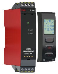
PR 9106A HART Transparent Repeater
Description
Application
- 9106A is a 1- or 2-channel isolated 1:1 repeater.
- The device supplies 2-wire SMART transmitters and can also be used for 2-wire SMART current sources. HART & BRAIN protocols are supported and are transferred bi-directionally.
- 9106A can be mounted in and receive signals from non-classified area or zone 2.
- For duplication/migration purposes, the outputs can be sent to two different DCS/PLC/HMI or any monitoring system.
- In safety applications (SIL loops), the 9106AxB can be used as a splitter with the following output configuration:
· When using 9106AxB in a SIL2 safety function, channel 1 is used for the safety loop. Channel 2 can be used for any non-safety device.
· For higher safety purposes (SIL 3), 9106AxB can be used as a splitter for SIL 3 loops. Channel 1 and 2 are then connected to the same safety PLC, where channel 2 is used as a redundant diagnostic channel. (For more information, consult the FMEDA Report and the Safety Manual).
Advanced features
- The detachable display and the green and red front LEDs indicate operation status for each channel.
- Monitoring of error events and cable breakage on input via the individual status relay and/or a collective electronic signal via the power rail.
Technical characteristics
- High galvanic isolation of 2.6 kVAC.
- Fast response time <5 ms
- High accuracy better than 0.1%.
- 2-wire transmitter supply >16 V.
Mounting
- The devices can be mounted vertically or horizontally without distance between neighbouring units.
Environmental Conditions
| Operating temperature | -20°C to +60°C |
| Storage temperature | -20°C to +85°C |
| Calibration temperature | 20…28°C |
| Relative humidity | < 95% RH (non-cond.) |
| Protection degree | IP20 |
| Installation in | Pollution degree 2 & measurement / overvoltage cat. II |
Mechanical specifications
| Dimensions (HxWxD) | 109 x 23.5 x 104 mm |
| Dimensions (HxWxD) w/ 4501 / 4511 | 109 x 23.5 x 116 / 131 mm |
| Weight approx. | 250 g |
| Weight incl. 4501 / 4511 (approx.) | 265 g / 350 g |
| DIN rail type | DIN EN 60715/35 mm |
| Wire size | 0.13…2.08 mm2 AWG 26…14 stranded wire |
| Screw terminal torque | 0.5 Nm |
| Vibration | IEC 60068-2-6 : 2007 |
| Vibration: 2…13.2 Hz | ±1 mm |
| Vibration: 13.2…100 Hz | ±0.7 g |
Common specifications
Supply |
|
| Supply voltage | 19.2…31.2 VDC |
Isolation voltage |
|
| Test /working: Input to any | 2.6 kVAC / 300 VAC reinforced isolation |
| Analog output to supply | 2.6 kVAC / 300 VAC reinforced isolation |
| Status relay to supply | 1.5 kVAC / 150 VAC reinforced isolation |
Response time |
|
| Response time (0…90%, 100…10%) | < 5 ms |
| Fuse | 1.25 A SB / 250 VAC |
| Max. required power | ≤ 1.1 W / ≤ 1.9 W (1 ch. / 2 ch.) |
| Max. power dissipation, 1 / 2 ch. | ≤ 0.8 W / ≤ 1.2 W |
| SMART bi-directional communication frequency range |
0.5…7.5 kHz |
| Signal / noise ratio | > 60 dB |
| Accuracy | Better than 0.1% of selected range |
| mA, absolute accuracy | ≤ ±16 μA |
| mA, temperature coefficient | ≤ ±1.6 μA / °C |
| Effect of supply voltage change on output (nom. 24 VDC) |
< ±10 μA |
| EMC immunity influence | < ±0.5% of span |
| Extended EMC immunity: NAMUR NE 21, A criterion, burst |
< ±1% of span |
Input specifications
Current input |
|
| Measurement range | 3,5…23 mA |
| 2-wire transmitter supply 9106A1x | >16 V / 20 mA |
| 2-wire transmitter supply 9106A2x | >15 V / 20 mA |
| Sensor error detection: Loop break 4…20 mA | < 1 mA |
| Input voltage drop, supplied unit | < 4 V @ 23 mA |
| Input voltage drop, non-supplied unit | < 6 V @ 23 mA |
Output specifications
Current output |
|
| Signal range | 3.5…23 mA |
| Load (@ current output) | ≤ 600 Ω |
| Load stability | ≤ 0.01% of span / 100 Ω |
| Current limit | ≤ 28 mA |
Status relay |
|
| Max. voltage | 110 VDC / 125 VAC |
| Max. current | 0.3 ADC / 0.5 AAC |
| Effect of external 2-wire supply voltage variation |
< 0.005% of span / V |
| Max. load resistance [Ω] | (Vsupply – 3.5) / 0.023 A |
| Max. external 2-wire supply | 26 VDC |
| Status relay output terminal 33-34: Relay function | N.C. |
| Programmable low setpoint | 0…29.9 mA |
| Programmable high setpoint | 0…29.9 mA |
| Hysteresis for setpoints | 0.1 mA |
| Max. voltage – hazardous installation | 32 VDC / 32 VAC |
| Max. current – hazardous installation | 1 ADC / 0.5 AAC |
| *of span | = normal measurement range 4…20 mA |
Observed authority requirements
| EMC | 2014/30/EU |
| LVD | 2014/35/EU |
| RoHS | 2011/65/EU |
Approvals
| UL | UL 61010-1 |
| EAC | TR-CU 020/2011 |
| DNV-GL Marine | Stand. f. Certific. No. 2.4 |
| SIL | SIL 2 / SIL3 certified & fully assessed acc. to IEC 61508 |