
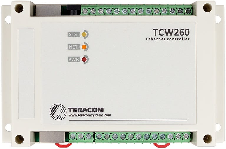
Description
The TCW260 is a versatile energy monitoring module designed with galvanic isolated digital and analog inputs, plus an RS-485 interface. Its four digital inputs are S0 hardware compatible, allowing integration with up to four energy meters that provide S0 pulse outputs, and can also be used with general dry contact sensors. The analog inputs offer flexibility, configurable for either current loop (0/20mA) or voltage (0/10V) modes, enabling connections to various voltage and current transducers. Through its RS-485 hardware interface, the module supports the Modbus RTU protocol, facilitating connections with up to 24 registers or devices.
This module allows for the configuration of up to 24 monitoring channels using all primary parameters from digital, analog, and Modbus RTU inputs. These channels can track general metrics like current or temperature, or cumulative values such as energy and volume, all viewable as both digits and graphs directly through a web interface. The TCW260 also includes robust alarm functionality, supporting up to 24 independent alarms across four customizable categories, which can also be graphically monitored. For seamless system integration, the module supports M2M protocols over Ethernet, including SNMP, HTTP API, and Modbus TCP, making it an ideal component for comprehensive energy monitoring systems.
Features
- Up to 24 channels for voltage/current or energy monitoring
- Up to 24 categorized alarms with flexible setup
- Graphs for monitored channels/alarms directly on the browser
- 4 isolated digital inputs with S0 interface (EN62053-31) compatibility
- ON/OFF and counter modes for the digital inputs
- 6 isolated analog inputs with 0/20mA or 0/10V modes
- RS485 isolated interface for up to 24 Modbus RTU registers
- Password protected WEB based configuration and control
- Data logger for 70000 records
- MQTT support
- Periodical HTTP Post with XML/JSON files for client-server systems
- HTTP API commands
- SNMP v.2 and v.3 support
- Dynamic DNS support of DynDNS, No-IP, and DNS-O-Matic
- Backup/Restore for easy device settings multiplications
- Remote firmware update over the WEB interface
Applications
- Еnergy monitoring and targeting for industry
- Energy cost optimization systems
- Energy consumption management systems
- Remote monitoring of renewable energy power plants
- General industrial processes monitoring
- Protocol conversion – Modbus RTU to Modbus TCP
Specifications
| Analogue Input | 0-10V or 0-20mA |
| Digital Input | Non-Isolated Dry contact, Max 5.5vDC. |
| Rating | 3A @ 24VDC or 30VAC |
| Modbus Interface | RS485 Modbus RTU |
| Internal Battery | CR1220 Back-up Lithium Battery |
| Power Supply | 10-28vDC |
| Power Consumption | 220mA @ 12vDC with Modbus power |
| Dimensions: | 145 x 90 x 40mm |
| Weight | 200g |
| Operating Temperature | -20 to -55°C (10-80%RH) |
| Warranty | 3 Years |
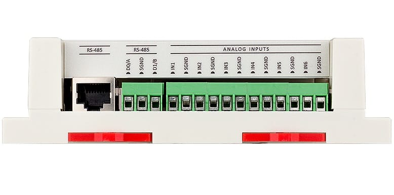
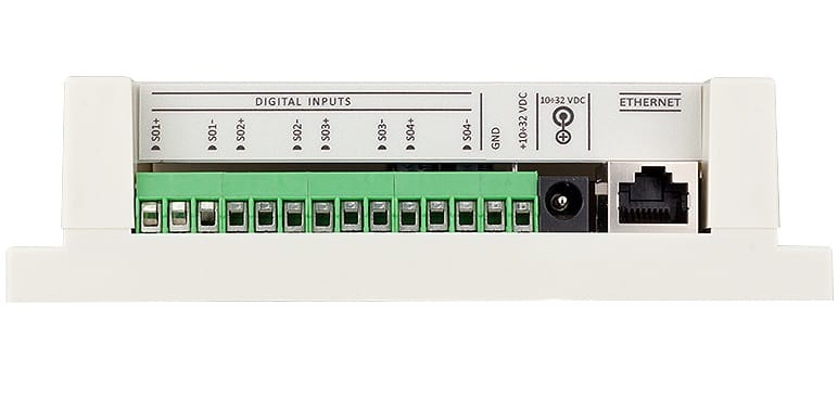
Connection Diagram
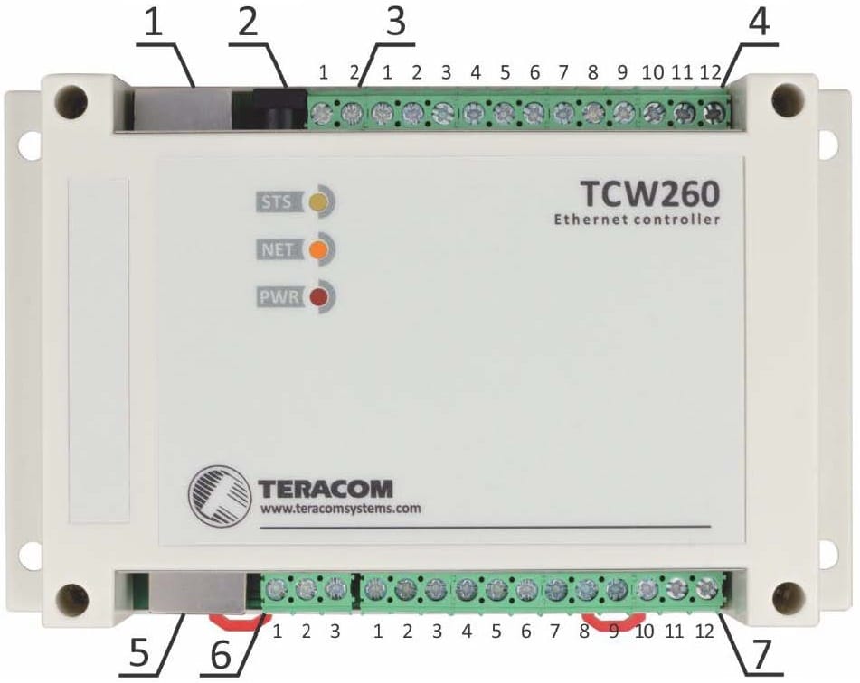
| Connector | Description | Connector | Description |
| Connector 1 | Ethernet – RJ45 | Connector 5, Pin 5 | RS485+ |
| Connector 2 | Power – 2.1×5.5mm connector, central positive | Connector 5, Pin 6 | Not Connected |
| Connector 3, Pin 1 | Power +ve | Connector 5, Pin 7 | +VDD |
| Connector 3, Pin 2 | Power -ve | Connector 5, Pin 8 | SGND |
| Connector 4, Pin 1 | S04- (SGND) | Connector 6, Pin 1 | RS485+ |
| Connector 4, Pin 2 | Not Connected | Connector 6, Pin 2 | SGND |
| Connector 4, Pin 3 | S04+ (Digital In 4) | Connector 6, Pin 3 | RS485- |
| Connector 4, Pin 4 | S0- (SGND) | Connector 7, Pin 1 | Analogue In 1 |
| Connector 4, Pin 5 | Not Connected | Connector 7, Pin 2 | SGND |
| Connector 4, Pin 6 | S03+ (Digital In 3) | Connector 7, Pin 3 | Analogue In 2 |
| Connector 4, Pin 7 | S02- (SGND) | Connector 7, Pin 4 | SGND |
| Connector 4, Pin 8 | Not Connected | Connector 7, Pin 5 | Analogue In 3 |
| Connector 4, Pin 9 | S02+ (Digital In 2) | Connector 7, Pin 6 | SGND |
| Connector 4, Pin 10 | S01- (SGND) | Connector 7, Pin 7 | Analogue In 4 |
| Connector 4, Pin 11 | Not Connected | Connector 7, Pin 8 | SGND |
| Connector 4, Pin 12 | S01+ (Digital In 1) | Connector 7, Pin 9 | Analogue In 5 |
| Connector 5, Pin 1 | Not Connected | Connector 7, Pin 10 | SGND |
| Connector 5, Pin 2 | Not Connected | Connector 7, Pin 11 | Analogue In 6 |
| Connector 5, Pin 3 | Not Connected | Connector 7, Pin 12 | SGND |
| Connector 5, Pin 4 | RS485- |