Downloads
TCG140-4 Remote IO Module
Description
The TCG140 is a versatile GSM-GPRS remote I/O module designed for distributed monitoring and control via mobile networks. It can operate as a standalone device or integrate into larger SCADA (Supervisory Control and Data Acquisition) systems. This module is equipped with a variety of inputs, including two digital “dry contact” inputs, two analogue inputs configurable for a 0-10V range, and an additional two analogue inputs that can be set via a GUI to either 0-10V or 0-20mA. Furthermore, it supports both 1-Wire and RS485 (Modbus RTU) interfaces, each capable of accommodating up to 8 sensors in total, distributed flexibly between the two. All monitored parameters are recorded in the device’s internal flash memory at predefined time intervals or upon alarm conditions, with log files capable of being periodically uploaded to a dedicated server via HTTP Post.
Beyond data acquisition, the TCG140 offers robust control capabilities. It features four relays with normally open and normally closed contacts, which can be activated remotely via SMS, call, or HTTP API commands, or locally triggered by an alarm state of a monitored parameter. The module can proactively initiate connections to remote servers via HTTP Post, sending an XML file containing current parameter values either periodically or when an alarm occurs. This HTTP Post can also receive an HTTP API command in response, enabling remote relay activation or setting changes. For comprehensive alerting, the TCG140 can send SMS messages and/or emails to up to five recipients in addition to HTTP Post alerts.
Features
- Quad-bands GSM connectivity
- Setup via USB (Windows setup program) or SMS
- 2 digital ”dry contact” inputs
- 1-Wire interface for up to 8 Teracom sensors
- RS-485 interface for up to 8 Modbus RTU sensors
- 2 analog inputs with 0-10vDC range
- 2 analog inputs with 0-10vDC or 0-20mA mode (WEB control)
- 4 relay outputs with NO and NC contacts
- Data logger for up to 70,000 records
- Periodical upload of data logger file to a remote HTTP server
- HTTP Post – XML data is sent periodically to a remote HTTP server
- HTTP API commands
- SMS alarm alerts (up to 5 numbers)
- Email alarm alerts (up to 5 email recipients), SMTP with TLS support
- Single call control for the relays from up to 5 numbers
- Firmware update over USB or GPRS
Applications
- Humidity, temperature and CO2 monitoring
- Mobile environmental monitoring for vehicles
- Street lighting control for smart cities systems
- Data logging of industrial processes
- Remote water pump station monitoring
- Drug and food facilities monitoring
Specifications
| Analogue Input | 0-10vDC or 4-20mA |
| Digital Input | Non-Isolated Dry contact, Max 5.5vDC. |
| Relay Output | NO or NC contacts |
| Rating | 3A @ 24VDC or 30VAC |
| Mechanical Endurance | 10 million operations |
| Digital Interface | 1-Wire and RS485, 5vDC excitation @ Max 200mA |
| Power Supply | 10-24vDC |
| Power Consumption | 340mA :@ 12vDC |
| Dimensions: | 158 x 119 x 32mm |
| Weight | 470g |
| Operating Temperature | -20 to +5°C (5-85%RH) |
| Warranty | 3 Years |
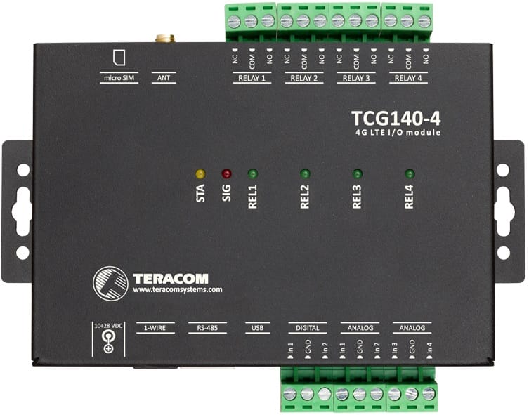
Connection Diagram
| Connector | Description | Connector | Description |
| Connector 1 | Power – 2.1×5.5mm connector, central positive | Connector 6, Pin 1 | Normally Closed Relay 1 |
| Connector 2, RJ-11 | 1-Wire Interface | Connector 6, Pin 2 | Common Relay 1 |
| Connector 3, RJ-45 | RS485 Interface | Connector 6, Pin 3 | Normally Open Relay 1 |
| Connector 4 | Mini USB | Connector 6, Pin 4 | Normally Closed Relay 2 |
| Connector 5, Pin 1 | Digital Input 1 (Din1) | Connector 6, Pin 5 | Common Relay 2 |
| Connector 5, Pin 2 | Digital Ground | Connector 6, Pin 6 | Normally Open Relay 2 |
| Connector 5, Pin 3 | Digital Input 2 (Din2) | Connector 6, Pin 7 | Normally Closed Relay 3 |
| Connector 5, Pin 4 | Analogue Input 1 (Ain1) | Connector 6, Pin 8 | Common Relay 3 |
| Connector 5, Pin 5 | Analogue Ground | Connector 6, Pin 9 | Normally Open Relay 3 |
| Connector 5, Pin 6 | Analogue Input 2 (Ain2) | Connector 6, Pin 10 | Normally Open Relay 2 |
| Connector 5, Pin 7 | Analogue Input 3 (Ain3) | Connector 6, Pin 11 | Normally Closed Relay 3 |
| Connector 5, Pin 8 | Analogue Ground | Connector 6, Pin 12 | Common Relay 3 |
| Connector 5, Pin 9 | Analogue Input 4 (Ain4) | Connector 7 | Normally Open Relay 3 |
| Connector 8 | SIM Card | ||
Pinout of Connectors
| RJ11 1-Wire Connector | RJ45 Modbus Connector | ||||||
 |
Pin | Description | UTP Wire Colour |  |
Pin | Description | UTP Wire Colour |
| 1 | 1-Wire Ground | White/Brown | 1 | Not Connected | Orange/White Tracer | ||
| 2 | 1-Wire Ground | White/Green | 2 | Not Connected | Orange | ||
| 3 | 1-Wire Data | Green | 3 | Not Connected | Green/White Tracer | ||
| 4 | 1-Wire Ground | White/Orange | 4 | RS485- | Blue | ||
| 5 | 1-Wire +VDD | Orange | 5 | RS485+ | Blue/White Tracer | ||
| 6 | 1-Wire +VDD | Brown | 6 | Not Connected | Green | ||
| 7 | +VDD | Brown/White Tracer | |||||
| 8 | GND | Brown | |||||
The last sensor in the chain must have a 120-ohm terminator installed in its free RJ-45 socket. A terminator is supplied with the controllers.


