
Description
The TCW122B-WD is a versatile IP monitoring module built for fail safe operation. It monitors the health of devices and networks by exchanging ICMP echo requests and replies (pings). When a ping fails to occur within a specified period, the module triggers a relay, enabling automated restarts of the monitored equipment.
Beyond its watchdog capabilities, the TCW122B-WD offers two digital and two analog inputs, along with two flexible relays that support both normally open and normally closed connections. It can also generate SNMP traps based on changes in temperature, humidity, analog voltage readings, and digital input states. Furthermore, the relays can be activated remotely through a web interface or SNMP commands, or automatically based on the success or failure of ping checks.
Features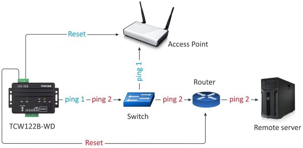
- Password protected, web-based configuration and control
- 2 digital inputs with ” dry contact” and “logic level” modes
- 2 analogue inputs with 0 to 60VDC range
- 2 relays with NO and NC contacts
- 1-Wire interface for up to 2 sensors
- SNMP v.1 support, SNMP trap alerts
- SNMP traps for alert conditions
- HTTP and SNMP port changing
- VLAN, MAC address filtering
- ICMP watchdog monitoring
- Remote firmware update
Applications
- Watchdog monitoring of small and medium networks
- Monitoring of temperature and humidity in server rooms
- Control and management of ISP networks
- Remote control of electric devices
Specifications
| Analogue Input | 0-60vDC |
| Digital Input | Non-Isolated Dry contact, Max 5.5vDC. |
| Relay Output | NO or NC contacts |
| Rating | 3A @ 24VDC or 30VAC |
| Mechanical Endurance | 10 million operations |
| 1-Wire Interface | up to 2 temperature (TST1XX) or temperature/humidity (TSH2xx) sensors |
| Power Supply | 10-14vDC |
| Power Consumption | 200mA :@ 12vDC |
| Dimensions: | 109 x 82 x 32mm |
| Weight | 110g |
| Operating Temperature | -20 to -55°C (5-85%RH) |
| Warranty | 3 Years |
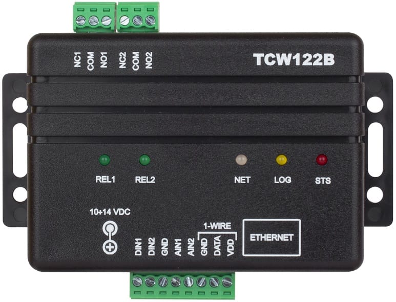
Connection Diagram
| Connector | Description | 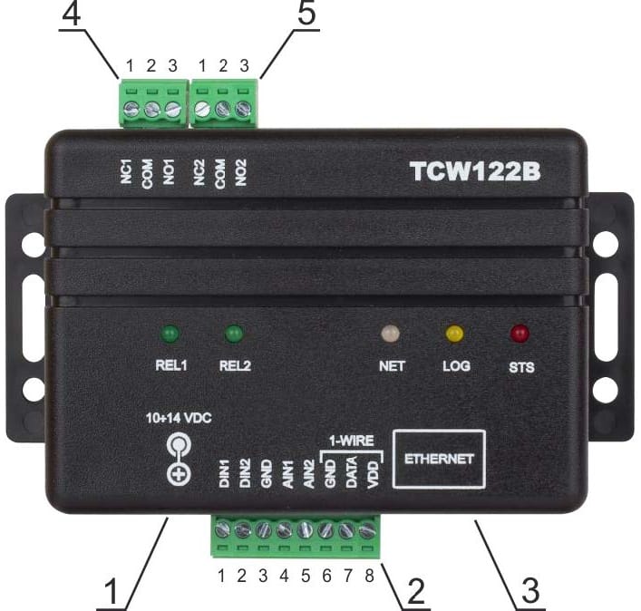 |
| Connector 1 | Power – 2.1×5.5mm connector, central positive | |
| Connector 2, Pin 1 | Digital input 1 (Din1) | |
| Connector 2, Pin 2 | Digital input 2 (Din2) | |
| Connector 2, Pin 3 | Ground | |
| Connector 2, Pin 4 | Analogue input 1 (Ain1) | |
| Connector 2, Pin 5 | Analogue input 2 (Ain2) | |
| Connector 2, Pin 6 | Ground | |
| Connector 2, Pin 7 | 1-Wire data | |
| Connector 2, Pin 8 | 1-Wire power supply | |
| Connector 3 | Ethernet – RJ45 | |
| Connector 4, Pin 1 | NC Relay1 | |
| Connector 4, Pin 2 | COM Relay1 | |
| Connector 4, Pin 3 | NO Relay1 | |
| Connector 5, Pin 1 | NC Relay2 | |
| Connector 5, Pin 2 | COM Relay2 | |
| Connector 5, Pin 3 | NO Relay2 |