Skip to content

omni instruments | sensors and data acquisition equipment

Sales & Technical Support

  • +44 (0) 1382 443000
  • info@omni.uk.com
  • Home
  • Custom Systems
  • System Hires
  • About
  • Contact
  • Home
  • Custom Systems
  • System Hires
  • About
  • Contact
Products
Edit Content
  • Data Loggers
  • Displacement
  • Display & Control
  • Flow Meters
  • Gas Detection
  • Gyros & Accelerometers
  • Level & Distance
  • Load Cells
  • Pressure Sensors
  • Radio & GSM Telemetry
  • Remote Monitoring
  • Serial Ethernet & ModBus
  • Solar & Wind Power
  • Subsea & Offshore
  • Temperature and Humidity
  • Test & Calibration
  • Torque Transducers
  • Vibration Monitoring
  • Voltage & Current
  • Water Quality
  • Weather Instruments
  • Accessories
  • Home
  • Custom Systems
  • System Hires
  • About
  • Contact
  • Home
  • Custom Systems
  • System Hires
  • About
  • Contact
Need Help?
£0.00 0 Basket
Product
Edit Content
  • Data Loggers
  • Displacement
  • Display & Control
  • Flow Meters
  • Gas Detection
  • Gyros & Accelerometers
  • Level & Distance
  • Load Cells
  • Pressure Sensors
  • Radio & GSM Telemetry
  • Remote Monitoring
  • Serial Ethernet & ModBus
  • Solar & Wind Power
  • Subsea & Offshore
  • Temperature and Humidity
  • Test & Calibration
  • Torque Transducers
  • Vibration Monitoring
  • Voltage & Current
  • Water Quality
  • Weather Instruments
  • Accessories
  • Data Loggers
  • Displacement
  • Display & Control
  • Flow Meters
  • Gas Detection
  • Gyros & Accelerometers
  • Level & Distance
  • Load Cells
  • Pressure Sensors
  • Radio & GSM Telemetry
  • Remote Monitoring
  • Serial Ethernet & ModBus
  • Solar & Wind Power
  • Subsea & Offshore
  • Temperature and Humidity
  • Test & Calibration
  • Torque Transducers
  • Vibration Monitoring
  • Voltage & Current
  • Water Quality
  • Weather Instruments
  • Accessories
£0.00 0 Basket
Home / Weather Stations and Instruments / 1405-PK-200
1405-PK-200

1405-PK-200

WindSonic M solid state sensor for wind speed and direction with integrated heating. Wind speed 0-60m/s, accuracy ±2%, wind direction 0-359°, accuracy ±2 degrees. Outputs RS232, RS422, RS485, Operating temperature -40 to +70°C, Storage temperature -40 to +90°C. Input voltage 24vDC, 4.2A @ 24vDC. Hard Anodised Aluminium Alloy Construction. Supplied with Windcom software, 9-way mating connector and mounting kit.

£1,647.00

Need help finding the right product?

CONTACT US

Downloads

Datasheet

Windsonic M Anemometer

  • Description

Description

This WindSonic M, Part Number 1405-PK-200. features serial outputs in RS232, RS422 and RS485 with NMEA 0183 or ASCII protocols, and optional heating. This version doesn’t include the optional analogue outputs and uses the 9-way connector. Other versions are available on the main page linked below.

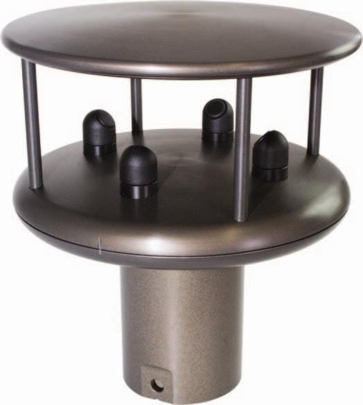
WindSonic M Ultrasonic Anemometer

FeaturesWindSonic75 Ultrasonic Anemometer Diagram

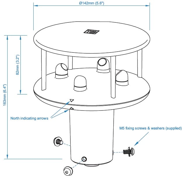
  • Wind Speed & Direction Sensor
  • 0-60m/s (116 knots) Wind Speed
  • 0-359° Wind Direction
  • WMO Compliant gust wind speed and directions
  • Vibration BS EN 60945:2002
  • Impact Resistance to UL2219 Class 1
  • NMEA Output
  • RS485 Modbus RTU Output
  • Hard anodised Aluminium alloy construction
  • Optional heating allow -40°C Operation
  • 24 Month Warranty
  • Free WindCom Software

Typical Applications

  • Data buoys
  • Marine vessels
  • Ports and harbours
  • Offshore helipads
  • Road & rail tunnels
  • Remote island weather stations
  • Coastal weather monitoring stations

Specifications

Wind Speed Range 0-60m/s (0-116 knots)
Wind Direction 0-360° (no dead band)
Starting Threshold 0.01m/s
Accuracy Wind Speed 2%, Direction 2° @ 12m/s
Resolution Wind Speed 0.01m/s, Direction 0.1°
Ultrasonic Output Rate 0.25, 0.5, 1, 2 or 4Hz
Parameters Speed & Direction or U & V Vectors
Units m/s, knots, mph, kph, ft/min
Power Supply 5-30vDC (Output Dependant)
Housing Material Al Alloy 6061 T6 with Hard Anodised finish
Operating Temperature -40 to 70°C
Size 142 x 163mm
Weight 0.9Kg

1405-PK-200 Output Options

Heating: Included and activate on temperature
Serial Outputs: RS232, RS422, RS485 and NMEA
Baud Rates: 2400 to 38400.
Anemometer Status: Supplied as part of standard message


Power Supply for Heated Variants

DC Power Supply Voltage: 10 to 30.0vDC.
AC Power Supply Voltage: 24V RMS AC ±10 % @50/60Hz.
12VDC Power Supply: Allow for 2.2 Amps @ 12V DC (nominal supply), 26W max.
24VDC Power Supply: Allow for 4.2 Amps @24v AC or DC (nominal supply) 100W max.
Standby Heater Current: Approximately 40mA.

For optimal performance, especially during initial start-up, a dedicated 24vDC heater supply capable of delivering a minimum of 6 Amps is recommended for the WindSonic M’s heating system for initial heating start-up surges. While the heater supply is electrically isolated from the sensor’s power, it is acceptable to use a common 24vDC source for both, if necessary. It is crucial to ensure that neither the sensor nor the heater supply connections are ever connected to the WindSonic M’s metal casing.

To maintain efficient heating, the length of the heater cable should be kept as short as possible to minimise voltage drops and ensure the anemometer receives the maximum available voltage. If longer cable runs are unavoidable, consider connecting spare wires in parallel to the designated heater pins. This effectively increases the wire gauge, reducing resistance and subsequent voltage drops across the cable.

The heating system in the heated WindSonic M operates autonomously, activated by internal temperature sensors when conditions likely to cause icing are detected. There is no external command to enable or disable the heating; it is continuously active and cycles on and off based on the sensed temperature. To completely disable the heating, the heater power supply must be physically disconnected. As a confirmation of functionality, a one-minute burst of heating will automatically occur upon powering up a heated WindSonic M unit, provided the heater supply is connected. Furthermore, the WindSonic M incorporates reverse polarity protection to prevent damage from incorrect power connections.

1771-PK-115

£272.00

Anodized Aluminium Bracket for mounting to pole and wall. Includes an aluminium sensor adaptor for WindSonic or MaxiMet, fully anodised to reduce corrosion. The Bracket uses a mounting clamp suitable for attaching to a vertical pipe with a diameter of 30-58mm. When mounting the MaxiMet, consider the position, orientation and alignment of the unit. Mount at the top of a pipe to ensure a clear unobstructed measurement view. Kit includes stainless steel mounting bolts, multiple earth points and wall / pole mounting kit
MORE INFO
Add to basket

1405-PK-111

£62.00

Spare WindSonic Connector suitable for WindSonic M with serial outputs only. 1405-PK-111 consists of 9-Way Connector Head, Part Number CL1F1201, and Connector Female Contact, Part Number CM10SC10MQ, Sealing Gland Clipper Size 1, Part Number CL101021
MORE INFO
Add to basket

links

  • About
  • Contact
  • Custom Systems
  • Privacy & Cookies
  • Terms & Conditions

omni instruments

Omni Instruments Ltd,
Unit 1, 14 Nobel Road,
Wester Gourdie Industrial Estate,
Dundee, DD2 4UH, UK

Sales & Support

  • +44 (0) 1382 443000
  • info@omni.uk.com

Payments

mastercard-color
visa-color
amex-color
Copyright Omni Instruments 2025 | Design. Build. Host.

We are here to help

Need help with your products or have a question for us on our custom systems? Use the form below to send us a message and our experts will be in touch to help.

Call us on +44 (0)1382 443000

Enquire now